
AMALGATONE
HYBRID COMPRESSOR — MORPHING DYNAMICS & ANALOG COLORATION
Introduction
Amalgatone is a hybrid compressor designed to deliver the ideal dynamic response for any source in a single plugin. By continuously morphing between classic compression topologies (FET, Opto, Tube), it lets you shape both the dynamic ballistics and harmonic coloration of each analog circuit to dial in the perfect sweet spot for your mix.
Interface Overview
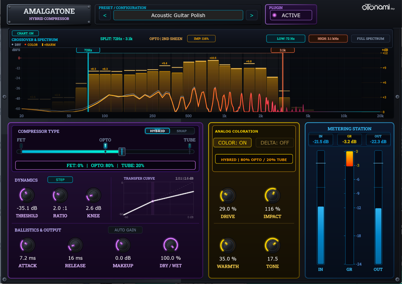
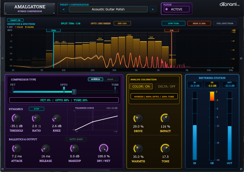
Amalgatone is divided into five intuitive sections: The Top Menu Bar [1] for click-free master bypass and preset management; the Spectrum Chart Section [2], which combines real-time harmonic visualization with adjustable high- and low-pass split-band filters to target specific frequencies; the Compressor Control Section [3] for morphing between circuit styles and dialing in dynamics, reaction times, and gain staging; the Coloration Control Section [4] for sculpting analog-inspired saturation, warmth, and tone; and the Meter View [5] for precision monitoring of input, gain reduction, and output levels.
[1] Top Menu Bar — Master Bypass & Presets
The Top Menu Bar handles global session control and preset management, allowing you to bypass the plugin with one click and quickly save or recall your settings.
[2] Spectrum Visualizer & Split-Band Filtering
This section combines real-time spectral visualization with phase-coherent high- and low-pass filtering. It displays the compression applied to the main signal alongside the harmonic impact of the coloration.
[3] Compressor Control — Morphing, Dynamics & Ballistics
Controls the core topology, compression curve, ballistics, and gain staging. Morph seamlessly or lock into three discrete compressor styles. Includes auto-gain compensation and a dry/wet mix control.
[4] Coloration Control — Analog-Inspired Harmonic Saturation
Positioned post-compression, the Coloration Engine continuously blends classic analog saturation—allowing you to morph smoothly between FET odd-order bite, Opto 2nd-order warmth, and Tube 2nd- and 3rd-order harmonic density.
[5] Meter View — Level & Gain Monitoring
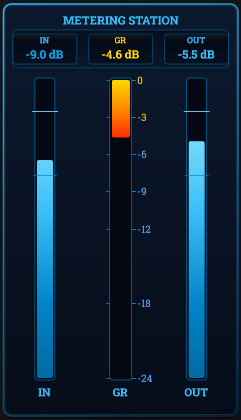
The Meter View delivers precise visual feedback and digital peak readouts to monitor input, gain reduction, and output levels.
1. Header Bar, Preset Management & Master Bypass
Located across the top edge of the interface, the Header Bar handles session-wide operations, instant preset recall, and seamless A/B comparison.
Master Bypass Button (ACTIVE / BYPASS)

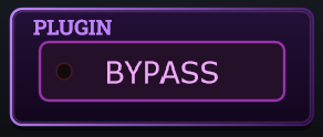
Clicking the ACTIVE / BYPASS button toggles the entire plugin between active processing and true bypass.
Equal-Power Crossfade DSP: Amalgatone executes a dedicated 15 ms equal-power linear crossfade as “smoothed Bypass”. This allows producers to toggle bypass during live playback without interrupting audio.
Preset Station & Preset Management
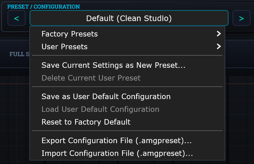
- Previous / Next Buttons (< / >): Instantly cycle backward and forward through available presets.
- Preset Name Display Button: Displays currently loaded configuration. Clicking opens a menu with:
| Menu Command | Function & Behavior |
|---|---|
| Factory Preset |
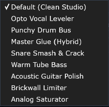 Allows the selection of official Amalgatone presets. Nine basic default presets are included. |
| User Presets |
Gives access to previously user saved presets.

|
| Save Current Settings as New Presets | Saves the current Plugin configuration. |
| Save as User Default Configuration | Saves the current Plugin configuration as default when using a new session of the plugin for the first time. Overwrites the Default “Clean Studio” preset. |
| Reset to Factory Default | Instantly reverts all controls back to the default Amalgatone configuration “Clean Studio”. |
| Export / Import Configuration file | Files are saved as .amgpreset and are standard UTF-8 XML documents storing the exact value of all 20 plugin parameters. You can open and edit them with any editor. |
2. Real-Time Spectrum Visualizer & Split-Band Filtering
The Spectrum Visualizer provides immediate visual feedback on incoming dynamics and harmonic coloration while offering phase-coherent split-band frequency isolation.
Visualizer (ON / OFF)
Toggles the real-time spectrum display on or off to conserve CPU resources. Real-time FFT analysis and curve rendering place a continuous load on your graphics processor—especially in large sessions or on high-resolution displays.
Disabling the display only turns off graphical rendering; all high- and low-pass filtering remains fully active on your audio.


Real-Time Spectrum & Harmonics
The real-time analyzer delivers detailed, lag-free visual feedback across the full 20 Hz – 20 kHz spectrum.

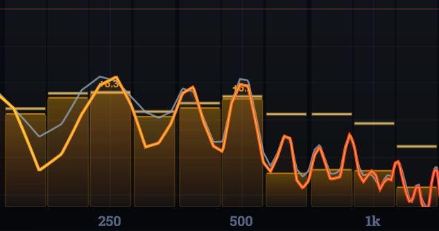
- DRY (Gray): Displays the uncompressed, uncolored input frequency spectrum (-60 dB to 0 dBFS) to serve as your clean reference.
- Color (Multi-Tone Gradient): Displays the processed output spectrum. The glowing curve uses a frequency-graded spectrum from warm amber (Lows) to electric cyan (Highs).
- 30-Band Background Harmonic Meter1: Vertical bars that track the saturation boost added by the Coloration Engine (+0 to +12 dB scale on the right edge). Responsive peak markers catch fast harmonic spikes, showing you exactly where tonal character is being injected.
The bars and active badges dynamically adapt their color to the dominant circuit topology in the blend:
- Neon Cyan: FET Circuit (Fast Odd-Order)
- Golden Amber: Opto Circuit (2nd-Order Sheen)
- Fiery Crimson: Tube Circuit (Triode Density)
1 Technical Note: The meter is divided into 30 standardized 1/3-octave frequency bands—matching how the human ear naturally groups sound. Each band uses peak-held ballistics to temporarily freeze at the highest transient level, displaying the exact boost in decibels.
Split-Band Crossover Filters
Interactive split-band crossover filters let you visually drag boundaries across the spectrum.
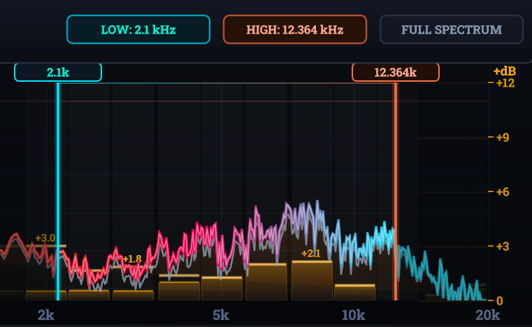
Direct Graph Control: Click and drag the vertical boundary lines directly on the spectrum display to sweep your low and high cutoff frequencies visually. Double-click a line or hit FULL SPECTRUM to quickly reset boundaries to default.
The transition is perfectly seamless and transparent, using phase-coherent crossovers to prevent any phase cancellation or frequency dips where the bands meet2.
Crossover Controls (Top-Right Buttons)
- FULL SPECTRUM: Resets both crossovers with one click, applying processing across the entire 20 Hz – 20 kHz range.
- LOW (High-Pass): Click to instantly engage a 120 Hz default cutoff (button illuminates). Click again when active to reset back to OFF (20 Hz).
- HIGH (Low-Pass): Click to instantly engage a 6 kHz default cutoff (button illuminates). Click again when active to reset back to OFF (20 kHz).
2 Transitions are handled by phase-coherent 24 dB/octave Linkwitz-Riley crossovers.
Status & Monitoring Readouts (Top Center)
Positioned along the top-center of the spectrum header, these real-time badges give you instant visual feedback on your active processing settings:

- Split Frequency Range: Displays the active crossover processing band (e.g.,
SPLIT: 120Hz – 6.0k) or indicatesFULL SPECTRUMwhen all frequencies are being processed. - Active Circuit Tag: Shows the dominant saturation topology and harmonic profile currently engaged (e.g.,
FET | FAST ODD,OPTO | 2ND SHEEN, orTUBE | TRIODE). - Impact Badge (IMP: %): A color-accented pill badge displaying the exact percentage of coloration and harmonic intensity dialed into the signal.
4th-Order Linkwitz-Riley (LR4) Phase Coherence
Standard crossovers often suffer from phase cancellation and volume dips where frequency bands meet. Amalgatone eliminates this by implementing 4th-order (24 dB/oct) Linkwitz-Riley dual crossovers, delivering two critical acoustic guarantees:
- Perfect Magnitude Flatness: The summed output maintains a strictly flat 0 dB frequency response across all crossover points with zero ripple or volume loss.
- Zero Phase Smearing: The high-pass and low-pass sections remain perfectly in-phase (360° alignment), preventing comb filtering and transient blurring.
When split-band mode is active, your audio is cleanly divided into three distinct paths—Sub-Bass (below the low cutoff), Target Band (compressed & colored), and High Air (above the high cutoff). Recombining these bands produces a transparent, artifact-free signal that preserves the natural punch and clarity of your original audio.
3. Compressor Control — Morphing, Dynamics & Ballistics
This section controls the core compression engine, combining seamless circuit morphing, dynamic thresholding, parallel mix balance, and auto-gain compensation in a single, intuitive layout.
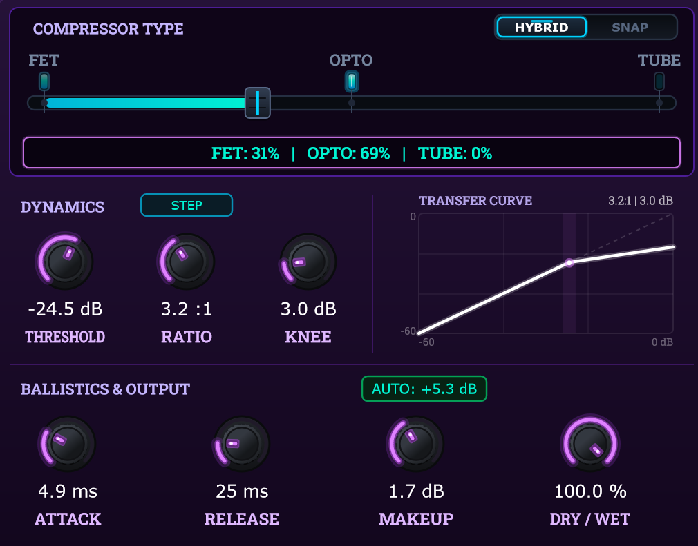
Style Slider — Continuous Morph

Drag the horizontal slider across the topology continuum. As you slide, Amalgatone’s engine dynamically reshapes the underlying ballistics—accelerating attack times in FET mode, introducing two-stage decay tails in Opto mode, and applying program-dependent release in Tube mode—all in real time with 30 ms click-free smoothing.
Style Mode Switch (HYBRID vs. SNAP)


HYBRID: Enables continuous, fluid morphing across circuits (e.g., 44% FET / 56% OPTO) to dial in custom intermediate blends.
SNAP: Locks strictly to pure FET, OPTO, or TUBE positions for instant classic hardware recall.
The Three Core Circuit Topologies
Circuit Architecture: Ultra-fast Field-Effect Transistor (FET) gain-reduction circuit modeled on vintage solid-state desk limiting.
Harmonic Profile: Generates punchy, symmetrical 3rd-order odd harmonics that add presence and aggressive transient bite.
Ballistics: Features Attack Acceleration (0.35 × base knob setting, scaling down to an ultra-fast 50 μs / 0.05 ms). Clamps onto unruly transients with lightning speed.
Knee Response: Sharp, focused transition knee (0.75 × width factor) for decisive, punchy dynamic control.
Circuit Architecture: Classic light-dependent resistor (photo-cell) and luminescent panel attenuator design.
Harmonic Profile: Produces warm, asymmetrical 2nd-order even harmonics via soft parabolic saturation for a silky vintage sheen.
Ballistics: Dual-stage optical memory ballistics. Recovers quickly from initial transients (1 × release time), then seamlessly drops into a slow, decaying luminescence tail (5 × slower) below 50% recovery.
Knee Response: Musical, wide expanding soft knee (1.15 × width factor) that gently hugs the signal as it crosses threshold.
Circuit Architecture: High-voltage remote-cutoff triode vacuum tube circuit utilizing bias-dependent dynamic gain reduction.
Harmonic Profile: Injects a rich, dense blend of both 2nd- and 3rd-order harmonics, imparting weight, analog warmth, and low-end glue.
Dynamic Ratio: Progressive ratio slope. Unlike fixed-ratio compressors, the compression ratio dynamically steepens the harder the input drives past threshold (+0.25 × excess dB).
Ballistics: Program-dependent release behavior—heavier gain reduction automatically slows down recovery to avoid distorting low frequencies.
Knee Response: Expansive, parabolic soft knee (1.50 × width factor) delivering the gentlest, most natural onset of compression.
Important Note: Understanding Circuit Ballistics vs. Knobs
When you move the Style morph slider, the Attack (ms) and Release (ms) knobs do not physically move on your screen. This is by design:
Knobs Set the Baseline Target: The Attack and Release controls establish your chosen macro timing (e.g., 10 ms attack and 100 ms release).
The Morph Slider Changes the Underlying Physics: As you morph between circuits, Amalgatone recalculates the mathematical envelope curves applied to those times under the hood:
- Sliding toward FET: The internal detection accelerates your attack setting (up to 0.35 × faster than the knob display) to clamp down instantly on transients.
- Sliding toward OPTO: Your release setting becomes the initial recovery rate, but below 50% recovery, the engine seamlessly engages a 5 × slower optical decay tail mimicking a physical photocell.
- Sliding toward TUBE: The release becomes program-dependent, automatically slowing down when the compressor experiences heavy gain reduction.
This intentional design preserves your dialed-in settings while delivering the authentic, fluid ballistics of each analog circuit in real time.
When morphing between two styles, the engine calculates a continuous mathematical blend of both circuits in real time. For example, at a 50% blend between Opto and Tube, the engine applies an equal 0.5 weighting across all DSP algorithms, simultaneously interpolating the knee geometry, dual-stage release ballistics, and harmonic saturation curves into a single hybrid equation.
Dynamic Topology Interpolation Reference
| Parameter | 100% FET | 50% FET / OPTO | 100% OPTO | 50% OPTO / TUBE | 100% TUBE |
|---|---|---|---|---|---|
| Attack Time Multiplier | 0.35x | 0.68x | 1.0x | 1.0x | 1.0x |
| Release Decay Model | 1.0x (Single-stage exp.) |
1.0x + 2.5x (Blended tail) |
1.0x + 5.0x (Dual-stage tail) |
2.5x tail + Program drag |
Program-dependent drag* |
| Knee Width Multiplier | 0.75x | 0.95x | 1.15x | 1.33x | 1.50x |
| Effective Ratio | Ratio | Ratio | Ratio | Ratio | Ratio + (0.25 × excess dB) |
| Harmonic Polynomials | 3rd Order (Odd) |
2nd & 3rd Order Blend |
2nd Order (Even) |
2nd & 3rd Order Blend |
2nd & 3rd Order Triode |
*Program-dependent drag: The release speed is not fixed—it automatically slows down the harder the music pushes into compression. The release speed adapts continuously across a 0 to 18 dB scale—starting at your exact knob setting for light hits and smoothly stretching recovery times as compression deepens to prevent low-end pumping.
Dynamics, Ballistics & Output
Provides precise control over gain reduction, attack/release ballistics, and output level blending.
Dynamics Controls (Curve Shaping)
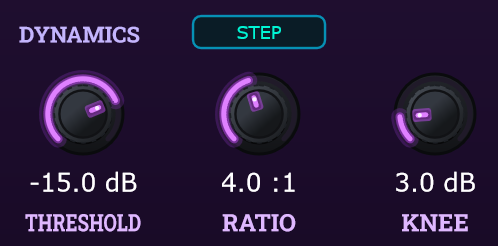
| THRESHOLD | -60.0 to 0.0 dB | Sets the level where compression begins. Lower values clamp deeper into the body. |
| RATIO | 1.0:1 to 20.0:1 | Gain reduction slope applied to signals exceeding threshold. |
| STEP BUTTON | Stepped / Free | Toggles snapping to classic steps: 2:1, 4:1, 8:1, 12:1, 20:1. Scroll mouse wheel over knob to cycle. |
| KNEE | 0.0 to 20.0 dB | 0 dB = hard knee (aggressive transient limiting); >6 dB = soft parabolic transition (invisible leveling). |
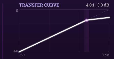
Interactive Transfer Curve Window
A dedicated display window rendering the input/output gain transfer function (-60 to 0 dBFS):
- Horizontal Axis: Input signal in dBFS.
- Vertical Axis: Compressed output signal in dBFS.
- Real-Time Transfer Curve: Updates instantly as you adjust Threshold, Ratio, and Knee, providing a clear visual representation of your compression curve and knee inflection point.
Ballistics & Output Controls
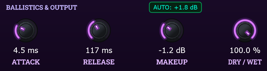
| ATTACK | 0.1 ms to 200.0 ms | Controls how fast gain reduction engages (scaled by 0.35× in FET mode down to 0.05 ms; 1.0× in Opto/Tube). Fast times (< 2 ms) tame harsh transients; slow times (> 20 ms) let transients punch through. |
| RELEASE | 10 ms to 1200 ms | Sets the envelope recovery rate to unity gain. Fast settings (< 50 ms) introduce rhythmic pumping and room energy; slow settings (> 200 ms) provide transparent dynamic glue. |
| AUTO GAIN | Toggle Button | Enables real-time analytical loudness compensation, eliminating psychoacoustic volume bias during auditioning. |
| MAKEUP | -12.0 to +24.0 dB | Manual output gain trim. When Auto Gain is active, this knob functions as an offset fine-trim. |
| DRY / WET | 0.0% to 100.0% | Crossfade between dry input and processed output for immediate parallel New York-style compression. |
4. Coloration Control — Analog-Inspired Harmonic Saturation
Placed downstream of the compression stage, the center-right Coloration Engine introduces tailored harmonic saturation to enrich warmth, overtone density, and acoustic presence.
Coloration Module Toggles
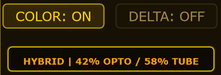
- COLOR (ON / OFF): Master enable/bypass switch for the saturation stage. Toggling to OFF passes the clean compressed signal directly to the output, bypassing drive, warmth, and tilt filtering.
- DELTA (ON / OFF): Auditions the isolated difference signal (wet minus dry), letting you hear exactly what the coloration engine adds.
- Circuit Style Readout: Indicates the active blend of modeled harmonic overtones (e.g.,
HYBRID | 44% FET / 56% OPTO).
Harmonic Sculpting Knobs
| DRIVE | 0% to 100% | Pushes audio into non-linear transfer curves (saturates earlier). |
| IMPACT | 0% to 200% | Scales both internal drive push and harmonic amplitude in the final mix. |
| WARMTH | 0% to 100% | Adds DC-bias skew for thick 2nd-order even harmonics. |
| TONE | -50 to +50 | 800 Hz hinge tilt EQ (vintage warmth to crisp top-end sheen). |
Under the Hood: Coloration Signal Flow & DC Protection
Audio entering the coloration engine traverses four sequential mathematical processing stages:
-
Asymmetrical Bias & Non-Linear Waveshaping: The Warmth control introduces controlled DC offset skew into the signal prior to non-linear transfer curves (
tanhandarctan). Pushing an asymmetrical signal through these topology-dependent transfer functions generates rich, musical 2nd-order even harmonics alongside odd-order bite. - 800 Hz Spectral Tilt Filter: A 1-pole low-pass/high-pass network (fc = 800 Hz) tilts the harmonic spectrum—attenuating or emphasizing overtone brightness without affecting the fundamental audio’s low-end phase.
- Discrete Leaky DC Blocker: Asymmetrical even-harmonic saturation naturally creates a DC offset drift. A recursive single-pole high-pass filter strips away DC bias with zero audible phase distortion in the musical spectrum.
- Harmonic Delta Extraction & Impact Scaling: The clean compressed signal is subtracted from the processed path to extract the isolated harmonic difference (Δ). This overtone matrix is scaled by the Impact control and summed back into the compressed signal.
5. Meter View — Level & Gain Monitoring
The Meter View delivers high-precision peak and gain-reduction metering to ensure effortless gain staging and dynamic control throughout your signal chain.
| Meter | Digital Readout | Scale & Ballistics | Visual Indicator Function |
|---|---|---|---|
| IN | -inf to +6.0 dBFS | Instant Peak & Smooth Decay | Upward-growing sapphire/cyan bar tracking raw input stereo peak level before compression. |
| GR | 0.0 to -24.0 dB | Instant Attack & Exponential Decay | Downward-growing amber-gold bar displaying active dynamic gain reduction. |
| OUT | -inf to +6.0 dBFS | Instant Peak (+6 dB Headroom) | Monitors post-processing output. Numerical readout illuminates in luminous ice cyan with a + prefix if signal exceeds 0 dBFS. |
Appendix: Shortcuts & System Specifications
Mouse Actions & Shortcuts
| Action | Target Control | Function & Result |
|---|---|---|
| Double-Click | Any Rotary Knob or Slider | Instantly resets parameter to factory default setting. |
| Ctrl / Cmd + Drag | Any Rotary Knob | Engages ultra-fine precision decimal adjustment mode. |
| Mouse Wheel Scroll | Any Knob or STEP Button | Adjusts parameter values simply by hovering. On the Ratio knob (or STEP button), it steps through fixed ratios (2:1, 4:1, 8:1, 12:1, 20:1). |
| Shift + Drag | Ratio Knob (when Stepped) | Temporarily bypasses step snapping for smooth continuous tuning. |
| Click & Horizontal Drag | Low / High Cutoff Markers | Sweeps split-band crossover frequencies on the visualizer chart. |
System Specifications & Compatibility
| Supported Formats |
• VST3 (64-bit Windows, macOS Universal, Linux x64) • AU / Audio Unit (macOS Universal arm64 / x86_64) |
| Operating Systems |
• Windows: 10 / 11 (64-bit) • macOS: 11.0 Big Sur or later (Apple Silicon M1–M4 & Intel) • Linux: x86_64 (Ubuntu / Debian / Arch / Fedora, ALSA & JACK) |
| Sample Rates | 44.1 kHz, 48.0 kHz, 88.2 kHz, 96.0 kHz, 176.4 kHz, 192.0 kHz |
| Processing Latency | 0 Samples (Zero-Latency) — Ideal for live tracking and low-latency monitoring. |
| Installation Paths |
• Windows VST3: C:\Program Files\Common Files\VST3\Amalgatone.vst3• macOS VST3: /Library/Audio/Plug-Ins/VST3/Amalgatone.vst3• macOS AU: /Library/Audio/Plug-Ins/Components/Amalgatone.component• Linux VST3: ~/.vst3/Amalgatone.vst3 (or /usr/lib/vst3/)
|
| Distribution Packages |
• Windows: Inno Setup Installer (.exe) & Portable (.zip)• macOS: Signed & Notarized Apple Installer ( .pkg)• Linux: Portable Archive with install.sh (.tar.gz)
|
| License & Royalties | 100% Free • Full commercial rights (commercial mixing, film scores, sound design). |
Keep a Copy in Your Studio
Download the complete print-ready PDF Operations Manual for offline studio reference.